- Home
- News & Events
- News
- Key Cable Considerations for Harsh-Environment Applications in the Medical and Solar Energy Markets
April 01, 2021
<< Back
Key Cable Considerations for Harsh-Environment Applications in the Medical and Solar Energy Markets
When it comes to harsh-environment applications, determining the appropriate interconnect solutions is essential for delivering high-reliability electrical and mechanical performance over long product lifetimes. This is especially true for medical and solar energy applications, which rely heavily on wire, cable, and connector solutions to transfer sufficient power and signal to charging devices and communication systems. However, with so many different connectivity factors to consider, it can be difficult to feel confident that you’re making the right choices. Here we’ll address several key cable considerations for high-reliability, harsh-environment applications in the medical and solar energy markets.
Cable Considerations for Harsh-Environment Medical Applications
1. What type of power and/or signal will be routed through the cable? Identifying the type of signal the cable will be carrying — for instance, an analog signal generated by an MRI body coil — is the first consideration when specifying cables for medical applications, because that information will determine the compatibility of the power and signal wires integrated into the same cable. Cables with a higher level of integration have fewer openings in the jacketed enclosure, which is especially critical in harsh environments exposed to moisture and liquid hazards. High-integration cables also enable designs with fewer connections, which can simplify and hasten assembly and installation procedures address on-site or in the field.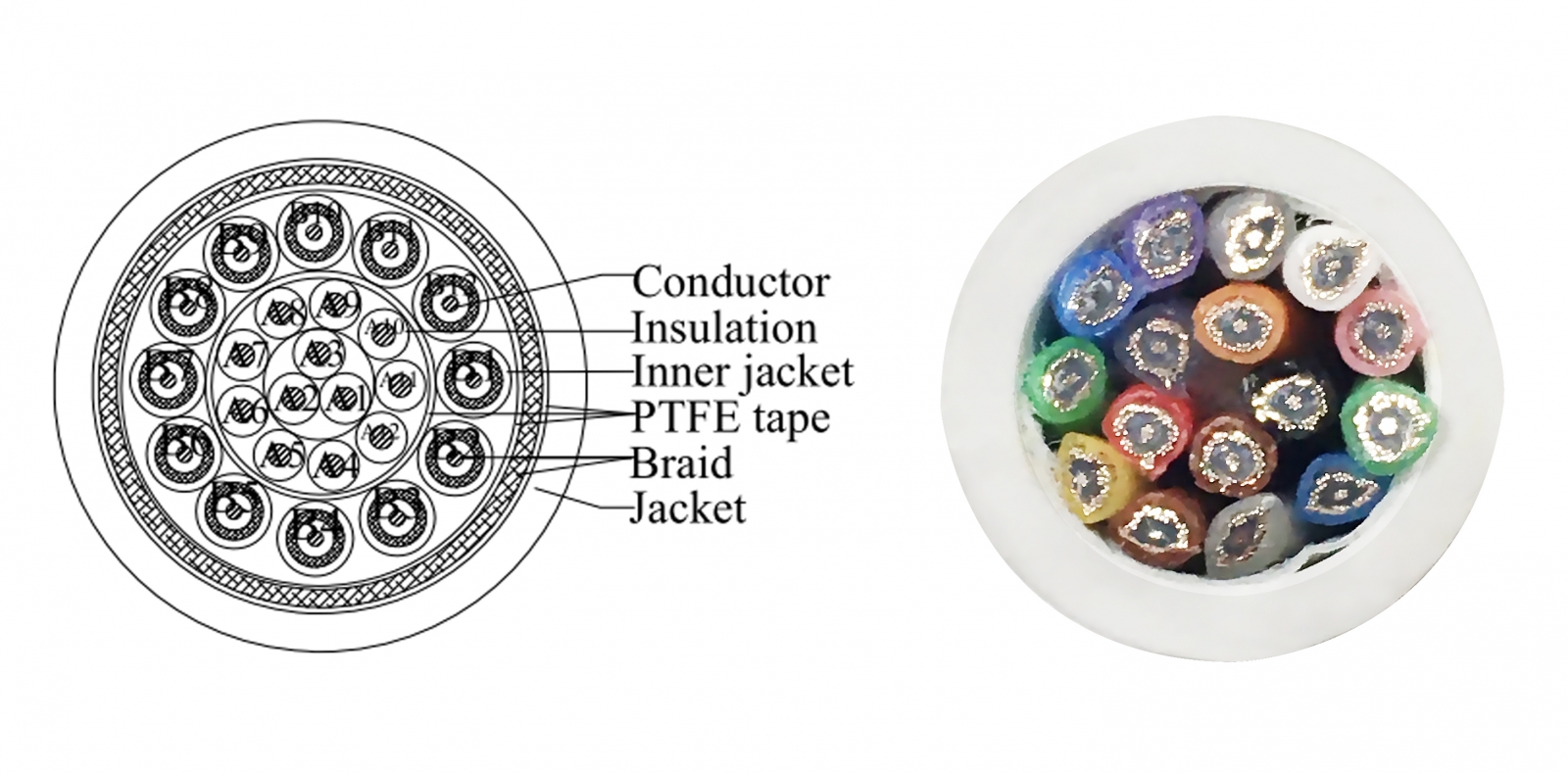
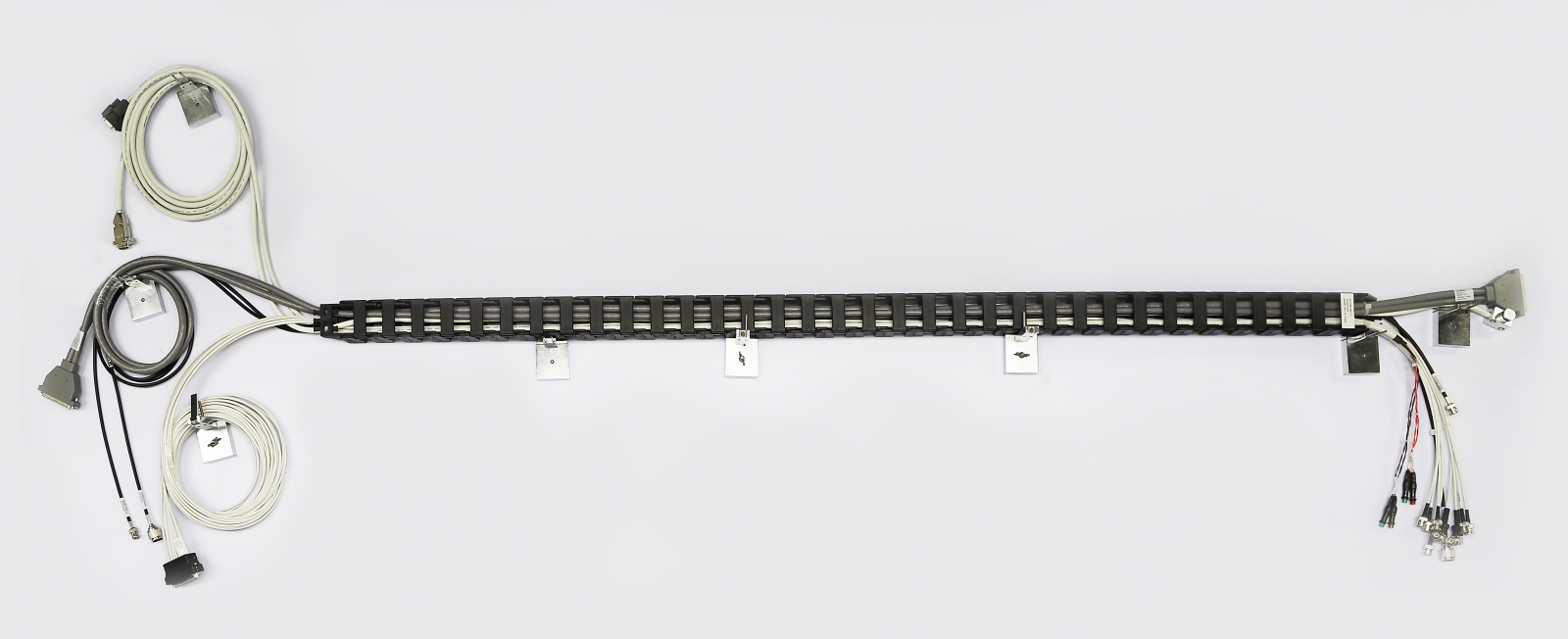
2. What are the operating conditions for the cable carrier? Many medical applications, including MRI machines and robotic surgery equipment, employ cable carriers to safely and effectively guide flexible electronic cables connected to moving machinery. Cable carriers relieve stress and reduce wear on equipped cables and are available in a variety of sizes, materials, and configurations to satisfy a broad range of application environments and operating conditions.
Conditions that can impact the durability and life cycle of the cables within cable carriers include:
- The radius of the cable carrier (maximum bend)
- The speed at which the cable carrier is required to travel
- The number of cycles per minute required of the cable carrier
- The maximum acceleration and deceleration rate of the cable carrier
- The total number of complete motion cycles required to match the equipment lifetime
It is critical to consider these factors when specifying cable that will be used in a cable carrier. The best cable selections will be closely matched to both the requirements of the cable carrier and overall electronics system, not only in terms of optimal power and/or signal transfer but in terms of durability and longevity as well.
3. Do the selected cables meet the application’s lifecycle requirements? Another critical step in the medical cable specification process is ensuring that the specified cable meets or exceeds the lifecycle required by the medical equipment it’s being designed into. Ideally, specified cables will not only fail to break down over the expected product lifetime; they will also deliver the performance levels required under anticipated operating conditions for the full duration of their rated lifetime.
One way to verify cable performance in terms of application lifecycles is to have the original equipment manufacturer (OEM) set up a field simulation equipped with the cable. Another approach is to have test and measurement specialists subject the cable to an array of specified environmental and operating conditions designed to mimic a real-world simulation. After either simulation, all of the cable’s electrical and mechanical characteristics should be carefully measured and compared to its initial specifications, prior to its employment in the simulation. If the cable was properly specified, there should be no more than a 10% difference between the measurements taken prior to the simulation and those recorded after the simulation.
4. What can be done to prevent the degradation of the cable? If the selected cable doesn’t perform successfully in field or lab simulations, it doesn’t necessarily mean that the specification process must start anew. It’s possible that changes can be made to the cable composition and/or structure to improve its performance and extend its lifecycle. For example, your cable supplier could reference the test results to:
- Reduce the diameter of the conductors to make the cable more flexible
- Introduce more flexible plastics into the cable composition
- Optimize the cable structure to better protect the wires and prevent performance issues
Cable Considerations for Harsh-Environment Solar Energy Applications
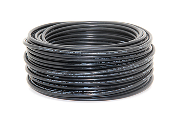
1. What is the electrical rating, rated voltage, and rated current required for the application? Since most of the electronics that comprise solar energy systems are installed outdoors and, as such, exposed to the weather, the connectivity components designed into this equipment must be ruggedized for both high power handling capabilities and harsh outdoor environments.Outdoor hazards can generally be addressed through materials selections, such as UV-resistant cable jackets, and protective accessories like conduit and heat-shrink boots and tubing.
To address high-power hazards, calculate the technical specifications by confirming the system’s voltage range, identifying string currents at different environments and whether it’s a DC or AC system, and addressing other pertinent operating conditions. Once confirmed, you’ll need to:
- Determine the cable size needed and the appropriate unit of measure (e.g., AWG for the U.S. or square millimeters for Europe), in addition to the number of cable strands needed and suitable dimensions for the outer cable diameter
- Identify the derating factor, which is a standard calculation applied to photovoltaic panel output to account for reduced power levels in real-world operating conditions, such as dirt accumulating on the panels, wiring losses, snow cover, and panel aging
- Calculate the copper resistance and anticipated power loss, if applicable
2. Which safety standards apply? Cable solutions designed into solar energy equipment must meet certain safety standards, which can vary depending on the geographic location of the installation. Three of the most common safety standards solar cabling must comply with are UL4703 for installations in North America; EN50618 and IEC62930 for installations in Europe, Southeast Asia, the Middle East, and China; and S-JET for installations in Japan. It is possible for a single cable to comply with multiple certifications, and it can be wise to specify such solutions when working with global OEMs.
3. Are there any special requirements? Since solar energy equipment is subject to hazards stemming from both high power levels and harsh environments, the cables designed into this equipment often have additional requirements. For instance, many solar cables require specific cable jacket and insulation material, such as halogen-free cross-linked polyolefin (XLPO), which is halogen-free, or cross-linked polyethylene (XLPE), which is ozone-resistant and less susceptible to environmental stress cracking than many other materials. Other special requests can include:
- Tinned copper strands for well contact and assembly
- UV and ozone resistance
- Flame retardance
- Halogen-free materials
- RoHS compliance
- Direct burial ratings so that no protective conduit is required
- Smoke emission standards compliance
- Acid and alkaline resistance
Addressing these key medical and solar cable considerations early in the design cycle will help make the specification and implementation processes more efficient and will better ensure that the specified cables deliver the high reliability, durability, and performance these harsh-environment applications demand.